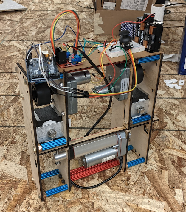
Project Overview
Goal: Design a wall-climbing robot for a ship hull tank inspection and maintenance. The system should be able to attach, detach from the wall, counter gravity, move vertically on the wall, transverse obstacles in a confined space and can carry a payload of at least 3lbs.
Final Deliverable: However, due to the impact of the COVID-19 and the limitation of time, we want to at least achieve some of the basic functions of the wall-climbing robot. The deliverable goals are that the system should be able to attach, detach on the wall, counter gravity and move on the vertical wall before the end of this quarter, because these are the basic functions of the wall-climbing robot.
Modeling and Analysis of System:
Modeling in CAD
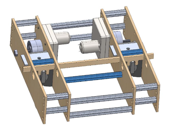
Our climbing robot was modeled in CAD where the design continued to progress and improve throughout our timeline. The CAD is where we get our first physical model in terms of accurate dimensions which leads to planning ahead.
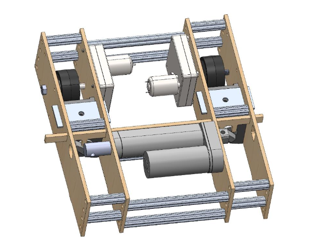
Chassis
We started with a basic chassis which would support agile manufacturing where changes could be made to the design when necessary. It consists of laser cut pieces of wood and aluminum churro to construct a rectangular chassis. This construction supports the direction of loading.
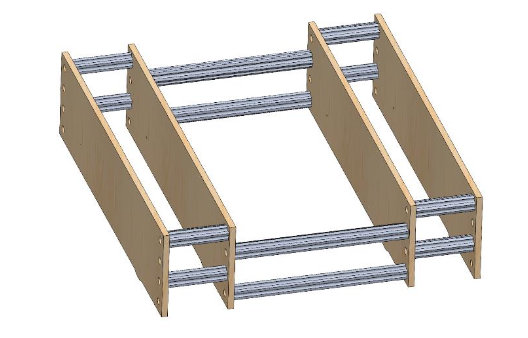
Wheels
The wheels are the critical point of the robot which both support the vertical
(gravity) and horizontal (magnetic) forces acting on the robot. They need to be sturdy
and have an excellent coefficient of friction. The wheels we chose were 2-inch stealth
wheels with a hex shaft bore
Motors
The motors are small 12-volt DC motors which come with an integrated gearbox allowing the ideal torque (40 in-lbf) for lifting the robot upward via driving the wheels. The gearbox has a face mounting design which assembles easily with the chassis.
Magnets
When considering magnets, the simplicity of a permanent magnet was advantageous to our short timeline. We repurposed the magnetic bases found in machine shops. They have switches which can orient the magnetic field to appear as on or off (see Figure 8). Their base force is 176 lbs. with no gap. However, a gap has been integrated to allow chassis movement, so the applicable force is less.
Linear Actuator
The magnetic switches are normally operated by human hands. To automate thisprocess, we have coupled together the two magnetic switches to a linear actuator, turning the linear motion into rotational motion. This linear actuator is a 12-volt motor and helical screw capable of pushing 35 lbf
Quantitative Results
To prove that the design works we performed analytical calculations based on a free body diagram of the robot attached to the wall. Some key numerical results are the required magnetic force of 240 N (54 lbf) and the torque of 2.5 N-m (22 in-lbf). These numbers correlate to a predicted chassis mass of 10 kg (22 lbs.).
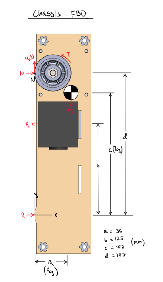
After constructing the Free body diagram, the specific inputs and outputs need to be specified. These quantities can be found in Table 2. The important inputs are as follows: The predicted mass, m of the robot is a conservative 10 kg. The friction coefficient, 𝜇 is 0.64, predicted by the stainless steel-60A rubber coefficient documented by Engineers Edge(1). Dimensions a through d are generated out of the CAD model. Specific outputs that are useful to know include the required magnetic force to stay statically attached to the wall, Fm (241.5 N), the normal force on the wheel, N (153.3 N), and the minimum required torque to climb the wall, T (2.49 N-m).


Controller Design, Analysis, and Implementation:
After we finish designing the chassis of our model, we immediately encounter another huge task, which is how to control our model. For controlling the model, we divide it into two parts. The first one is controlling the movement of the model in order to climb on the magnetic wall. The second one is controlling the switch of the magnetic base. In order to activate our model, we need a motor that can carry at least 3 pounds of payload capacity. Based on this requirement, we choose to use two CHM-1212-1M motors from Molon. It is a 12V DC motor which can provide 40 in-lb torque. On the other hand, we decide to use a linear actuator to control the switch of the magnetic base. In order to activate the DC motor and linear actuator, we use an Arduino board MEGA 2560 and a L298N motor driver for controlling.
Due to the current pandemic situation and limitation of time, we only consider the forward and backward motion of our model, which means we just need to adjust the rotation direction of the motor for clockwise or counterclockwise motion. For controlling the rotation direction of the motor, we need to change the direction of the current flow into the motor. One of the methods is using a H-bridge, which has four switching transistors with the motor at the center. By activating two switches at the same time, we can change the direction of the current flow. Meanwhile, the L298N is a dual H-bridge that can control the speed and the direction of the motor. That’s why we chose to use
L298N for motor control. When we look at the L298N module, the module has three screw terminal blocks. One of the blocks is used for connecting the linear actuator, and another block is used for wiring two 12V DC motors. The last block is used for grounding and output of the battery. The battery we are using to power the motors and Arduino is 12 volts.
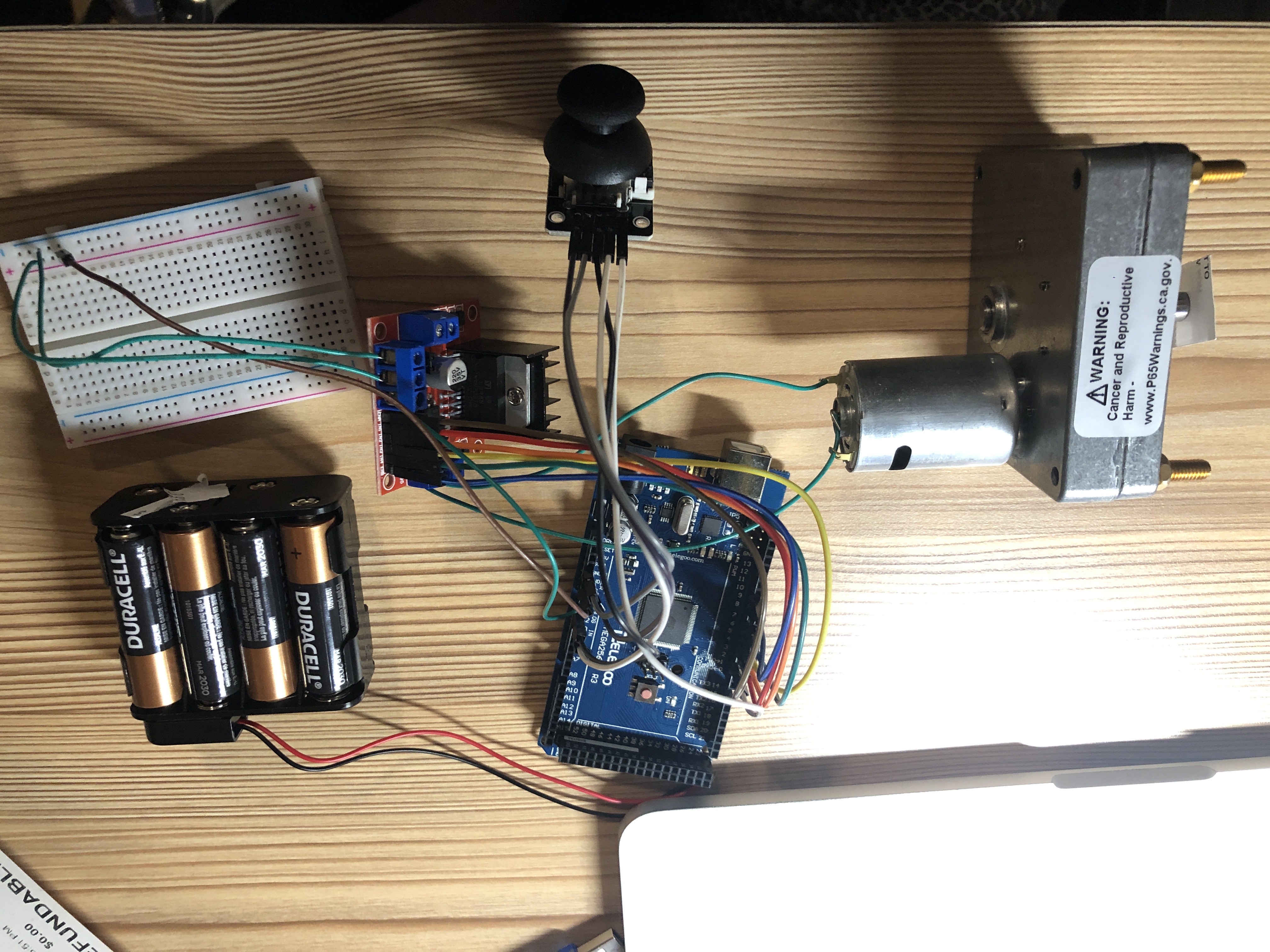
For the Arduino coding, we first need to define the pin and some variables. In the loop section, we will read the value of X and Y-axis from the joystick. The joystick is made of two potentiometers which connect to the analog inputs of the Arduino. The value of the joystick goes from 0 to 1023. These values help to define the X and Y-axis of the joystick. At the center of the joystick, the value for both potentiometers is around 512.
For considering the tolerance of the value, we will set the value from 470 to 550 as center. Therefore, if we move the Y-axis of the joystick backward and see the value goes below 470, we will set the two motors rotation direction to backward. The forward motion will have the same situation, but the value will be above 550.
For controlling motors, we came up with the easiest method to control the linear actuator and DC motors at the same time. We use one joystick x-axis to control the linear actuator and the other joystick y-axis to control DC motors. In order to achieve this controlling set up, we gave up the option of left and right movement for our model. Therefore, our model can only move forward and backward based on the current setting.
Design and Testing of Prototype
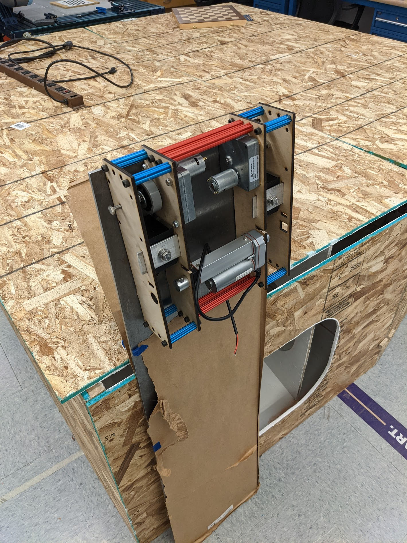
This second chassis wall has sufficient holes to hold the two motors, the magnets, and the linear actuators. It also has holes for a slider which will turn the magnetic switches on and off using the linear actuator. We manufactured different iterations of the slider to determine the most suitable geometry of the slider. The figure below shows the three different slider geometries. After testing the different sliders with the linear actuator, slider E was the best choice.
For our electronics test, we wanted to test that our two motors and linear actuator could be controlled independently from each other with the joystick. From an earlier test, the two motors are easily controlled with the joystick, moving clockwise and counterclockwise. During a recent test, we had issues with controlling both the motors and the linear actuator. When the joystick was moved in one direction, both the motors and the actuator moved. Ideally, we want to program the electronics so that moving the joystick “up and down” controls the direction of the motors and moving the joystick “left and right” controls the movement of the actuator. By the end of our project, we were able to have one axis of the joystick control the linear actuator and the other axis control the motors.
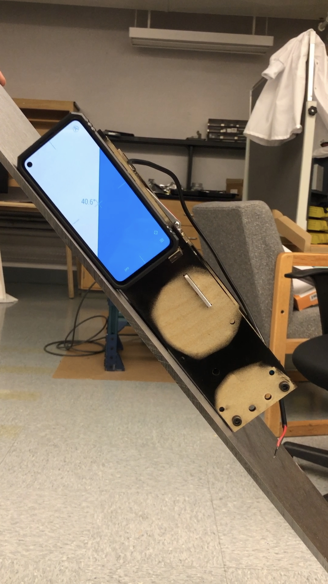
After complete assembly, our testing revolved around the robot’s motion. Once attached to the steel plate, we tested how well the robot could move up and down the plate. We found that the robot itself could move well up and down the plate. However, after adding a payload of about five pounds, the robot would not go up the plate. Then when we removed the payload, after a few more test runs, we began to encounter slipping with just the weight of the robot. We cleaned the wheels and the plate to help but even after, we still encountered slipping. We realized that there is a magnet gap “sweet spot” that allows the robot to go up the plate the best. Our most recent test allowed the robot to have a payload of approximately two pounds and was still able to move up the wall. However, like before, we kept encountering slipping after a few more test runs.
Results:

Goal number 1 (Attaching/detaching from a wall) depends on the magnets, slider, linear actuator, and our ability to control the linkage. There are two states where the robot is either attached or detached. Both states are fully satisfactory. Detached has no requirements besides being disconnected form the plate. In the attached case, the magnets solidly connect the robot to the steel plate. No expected interactions would cause the robot to unintentionally detach. The action of switching between states is an ideal function the robot should be able to accomplish, but there are some minor issues of the transition involving the movement of the slider. The slider linkage is pushed by the linear actuator, but the geometry of the linkage tends to bind where the actuator can not
continue pushing and there in a potential for the slider to snap. This can be fixed in a future iteration with different slider geometry. The whole goal is considered satisfactory since the transition sometimes works smoothly.
Goal number 2(Counter the force of gravity) depends on the magnets, wheels, drive motors and gearbox. This goal is considered satisfactory if the robot can be statically joined to the wall. The magnets provide enough normal force on the wheels such that the friction force of the wheels on the plate is equal to the force of gravity. The motors and their gearboxes have a high enough gear ratio and internal friction to hold the wheels still. No power in the motors is necessary resulting in fully satisfactory goal met.
Goal number 3(Climb a vertical wall) depends on the wheels and the motors. To be satisfactory the wheels must turn and lift the robot up and allow it to drop down. Referencing goal number 2, the robot already statically holds itself to the wall with no supplied power. Applying power should allow the robot to move up if the wheels do not slip due to a greater torque than wheel friction can counter. By applying power to the motors, the robot does ascend the wall, and a power reversal allow the robot to lower done, resulting in a fully satisfactory goal.
Goal number 4(Carry a 3 lb. payload) is satisfactory if the robot can carry a 3 lb. payload while still maintaining the 3 previous goals. This tests the limits of the robot and its ability to carry other tools. In our testing with a load cell, the final prototype starts slipping at 2.25 lbs. deeming this goal unsatisfactory. This occurred because the wheels did not have enough friction force to counter the weight of gravity.
Outcome:
- Designed and developed an embedded wall-climbing robot for the inspection and maintenance of ship hull tank
- Built and modeled in AutoCAD, implemented Arduino framework and API interface to control robot movement
- Constructed prototype board level digital and analog electronic circuits on L298N high current motor driver board
- Integrated the robot to avoid obstacles while carrying a maximum 2.25-pound payload, increased the payload efficiency by 50 % to ensure a 95% test coverage using finite element analysis by ANSYS Workbench